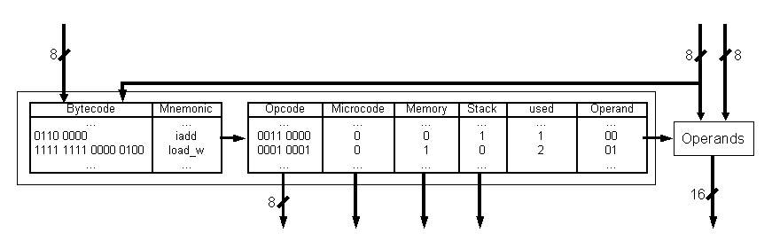
Figure 4.7:Transformation of Bytecode into Opcode
There are different groups of instructions: Kontrollfluß is for program flow controlling instructions. Stack, Load and Store belong to instructions for stack memory access (stack and local variables). The ones out of arithmetisch and logisch are for controlling execution in the arithmetic logic unit of the execution stage, groups If and Cmp hold branch instructions for the branch control unit. erweitert are all instructions which directly can address hardware as extended Bytecodes. For the resulting coding see section 4.5.
| BC-Mnemonic | Bytecode | Mnemonic | Opcode | Group | implemented as |
| aconst_null | 0x01h | push | 0100 0000 | Stack | directly |
| iconst_m1 | 0x02h | ||||
| iconst_0 | 0x03h | ||||
| iconst_1 | 0x04h | ||||
| iconst_2 | 0x05h | ||||
| iconst_3 | 0x06h | ||||
| iconst_4 | 0x07h | ||||
| iconst_5 | 0x08h | ||||
| bipush | 0x10h | ||||
| sipush | 0x11h | ||||
| iload | 0x15h | loadv | 0001 0000 | Load | directly |
| aload | 0x19h | ||||
| iload_0 | 0x1Ah | ||||
| iload_1 | 0x1Bh | ||||
| iload_2 | 0x1Ch | ||||
| iload_3 | 0x1Dh | ||||
| aload_0 | 0x2Ah | ||||
| aload_1 | 0x2Bh | ||||
| aload_2 | 0x2Ch | ||||
| aload_3 | 0x2Dh | ||||
| iaload | 0x2Eh | aload | 0001 1000 | Load | microcode |
| istore | 0x36h | storev | 0010 0000 | Store | directly |
| astore | 0x3Ah | ||||
| istore_0 | 0x3Bh | ||||
| istore_1 | 0x3Ch | ||||
| istore_2 | 0x3Dh | ||||
| istore_3 | 0x3Eh | ||||
| astore_0 | 0x4Bh | ||||
| astore_1 | 0x4Ch | ||||
| astore_2 | 0x4Dh | ||||
| astore_3 | 0x4Eh | ||||
| iastore | 0x4Fh | astore | 0010 1000 | Store | microcode |
| dup | 0x59h | loado | 0001 0001 | Load | directly |
| iadd | 0x60h | add | 0011 0000 | arithmetisch | directly |
| isub | 0x64h | sub | 0011 0001 | arithmetisch | directly |
| imul | 0x68h | mul | 0011 0100 | arithmetisch | directly |
| idiv | 0x6Ch | div | 0011 0101 | arithmetisch | directly |
| ineg | 0x74h | neg | 1100 0000 | logisch | directly |
| ishl | 0x78h | shl | 1100 0001 | logisch | directly |
| ishr | 0x7Ah | shr | 0011 0010 | arithmetisch | directly |
| iand | 0x7Eh | and | 1100 0011 | logisch | directly |
| ior | 0x80h | or | 1100 0100 | logisch | directly |
| ixor | 0x82h | xor | 1100 0101 | logisch | directly |
| iinc | 0x84h | iinc | 0011 0010 | arithmetisch | directly |
| ifeq | 0x99h | ifeq | 0101 0000 | If | directly |
| iflt | 0x9Bh | iflt | 0101 1001 | If | directly |
| if_icmpeq | 0x9Fh | braeq | 1010 0000 | Cmp | directly |
| if_icmplt | 0xA1h | bralt | 1010 1001 | Cmp | directly |
| load_word | 0xFFx04h | load_w | 0001 0001 | Load | directly |
| store_word | 0xFFx24h | store_w | 0010 0001 | Store | directly |
| read_pc | 0xFFx40h | r_pc | 1111 0000 | erweitert | directly |
| read_optop | 0xFFx43h | r_optop | 1111 0001 | erweitert | directly |
Address modes are limited in a stack architecture (discussed in section 4.3. That is why indirect address mode only exists with external memory access, for which only the instructions load_w and store_w are implemented in this prototype. All other instructions work on stack only and therefore with implicit address mode.
Additionally this decode stage determines needed operands in an operand fetch functionality. To do so it generates control signals like base register address and offset for the stack memory unit (see also section 4.4.5) so that all operands can be read for execution during the next clock cycle.
After the correct functionality of this pipeline is validated the instruction decode unit will be extended by the ability of recognizing data dependancies and to work them out by data forwarding. For this purpose additional control signals have been added to control the execution stage. The whole instruction decode unit is shown in figure 4.8.
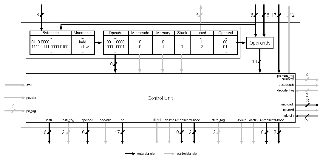
If a microcoded instruction is decoded a request with an address is sent to the Microcode-ROM Unit. This functional block sends back the sequence of directly executable instructions which is defined for replacing the decoded Bytecode. A state machine is used for this purpose. While no microcode is active it sends back 0xFFFFFFh which means normal decode action can be carried out to control execution.
This functionality is shown by the four concurrent processes in figure 4.16. One is for managing instruction data in buffering, decoding and shifting, the others generate output like instruction window full and the program counter to be passed with the next instruction.
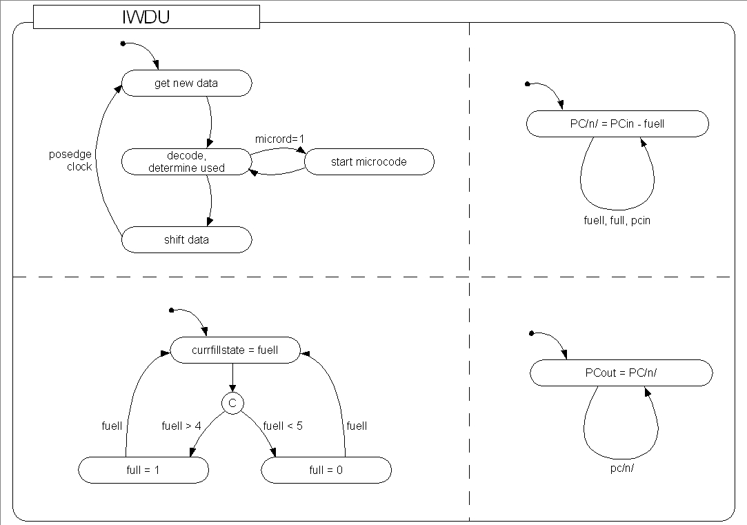
Figure 4.16: Statechart of the Instruction Window & Decode Unit